Selecting GNSS and Inertial for Intelligence, Surveillance and Reconnaissance
Inertial technology coupled with GPS/GNSS plays a critical role in the fast-growing field of intelligence, surveillance and reconnaissance (ISR) applications. This article covers the key factors to consider in selecting the best GPS/inertial integration for your particular ISR job.
With any tool, you need the right one for the job, and inertial technology comes in many forms, with many different capabilities. If optimally selected, your GNSS-aided Inertial Navigation System (GNSS/INS) will form the linchpin in positioning your ISR sensors for best results. Keys to consider are differences in errors that will inevitably be encountered: determining, relative to the desired level of performance, which errors are tolerable and which are not. This is called the error budget and is the first thing to review with knowledgable equipment suppliers.
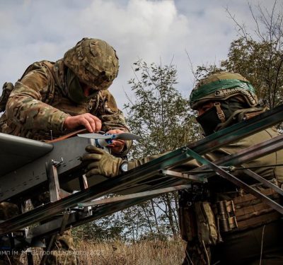
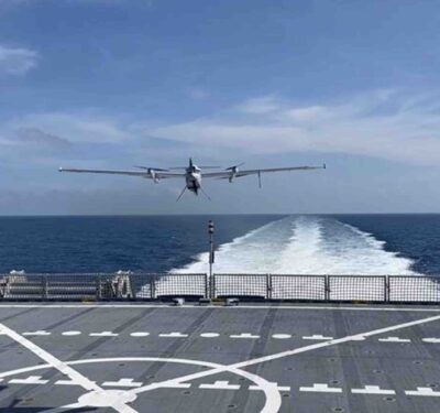
ISR technology finds increasing application in military, law enforcement, search and rescue, border patrol, disaster response and many other fields. In most cases, an airborne camera gathers data key to the operation, to locate, map and geo-reference points of interest.
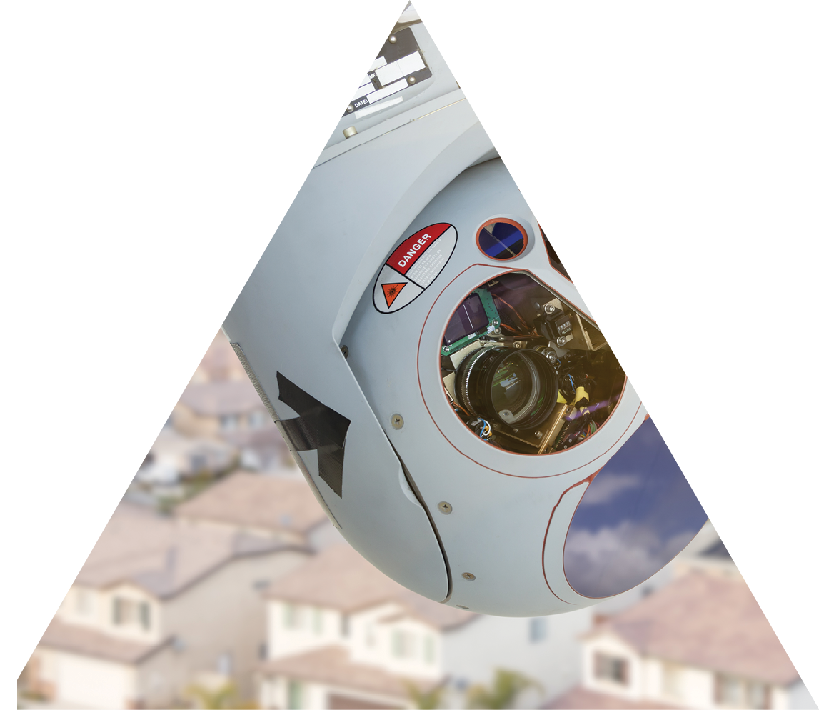
Typically, an electro-optical and/or infrared (EO/IR) camera is mounted on a gimbal, a pivoted support that rotates the camera around a single or a double axis. Gimballed systems are common on UAVs, aircraft and marine vessels. They enable pointing the sensor payload toward objects of interest, independent of the platform’s attitude or movement. That independent motion also allows for stabilization (or regulation), decoupling the high-frequency motion and vibrations of the platform or vehicle from those of the payload.
For a variety of reasons, gimballed payloads incorporate their own position and attitude (heading/yaw, pitch and roll) sensing in most applications, rather than relying on the platform’s GNSS/INS. The aircraft’s navigation system may not be accurate enough for geo-referencing objects seen from as far as 10,000 meters. In some cases, the aircraft’s navigation system may be mission-critical and thus unavailable to the ISR sensors. Finally, flexing of the aircraft introduces errors since the platform’s INS is typically mounted near the center of mass of the vehicle and not co-located with the gimbal.
POSITIONING THE SENSORS
For most gimbal-pointing applications including geo-referencing, the gimbal control system requires position data, which precludes a pure Inertial Measurement Unit (IMU) or Attitude Heading Reference System (AHRS) solution; it requires a GNSS-aided option. Even for applications where positioning is not required, the high-accuracy pointing requirements during dynamic motion mean that the degraded performance an AHRS suffers during such dynamics is unacceptable; again, a GNSS-aided solution is needed.
A GNSS/INS system is composed of inertial sensors (which come in a variety of grades), a high-sensitivity GNSS receiver, and Kalman filtering and algorithms. Measurements from the GNSS receiver are coupled with the inertial measurements to provide position, velocity, and attitude estimates of higher accuracy and better dynamic performance than a standalone GNSS, INS or IMU/AHRS can provide.
A GNSS/INS system typically includes a 3-axis gyroscope, a 3-axis accelerometer, a GNSS receiver, and sometimes a 3-axis magnetometer to determine a navigation solution. Each of these sensors contribute different measurements—and different potential errors—to the GNSS/INS system.
Combining GNSS and INS enables them to complement each other, overcoming some of the limitations they each face as standalone systems. A few issues remain to be addressed in an integrated GNSS/INS system.
This article covers how to select the right GNSS/inertial unit combination for a specific application, and how to integrate that into the full range of pointing, sensor, and geo-referencing systems.
DO I NEED A GNSS COMPASS?
A GNSS/INS provides accurate data under dynamic conditions, generally for platforms moving at 5 meters/second (roughly 11 mph) or faster. A single-antenna GNSS component is generally reliable for this type of application, being able to track heading through a process called dynamic alignment. This correlates accelerometer measurements with GNSS measurements to track heading in the presence of horizontal acceleration. This is not the same as course-over-ground of a GNSS system, but is rather the true heading of the system.
Since it relies on dynamic alignment, a single-antenna GNSS/INS will lose its ability to accurately track heading in applications where the platform is stationary or moving slower than 5 meters/second, such as helicopters, rotor UAVs, or marine vessels. Even large aircraft that endure long periods of straight and level flight may find that their attitude solution wanders during such periods of low dynamics. In these scenarios, a GNSS/INS with integrated GNSS-Compass is preferred.
A GNSS-Compass is a system composed of two GPS receivers connected to two external GNSS antennas some fixed distance apart. Differential GNSS calculations are used to determine the relative position of the two GNSS antennas to millimeter-level accuracy to measure the heading of the system. The heading accuracy of this GNSS-Compass is inversely proportional to the separation distance between the antennas.
VectorNav’s VN-300 and VN-310 GNSS/INS products are examples of dual antenna GNSS/INS systems. Advanced GNSS/INS systems with integrated GNSS-Compasses such as the VN-300 and VN-310 can automatically transition between the dual-antenna heading solution and dynamic alignment to output the most accurate heading, depending on real-time motion of the systems.
STANDARD GNSS VS RTK AND INDUSTRIAL VS TACTICAL GRADE INS
Inertial sensors come in different grades, depending on their gyroscope-induced error budgets. ISR applications typically require either industrial or tactical grade IMUs. There can be an order of magnitude difference between them.
RTK involves use of a base station on the ground in addition to the GPS/GNSS receiver onboard the aircraft, and yields a higher degree of positioning accuracy. RTK has its limitations, however: extra size, weight and power, cost, additional hardware with base station, range to base station, and so on.
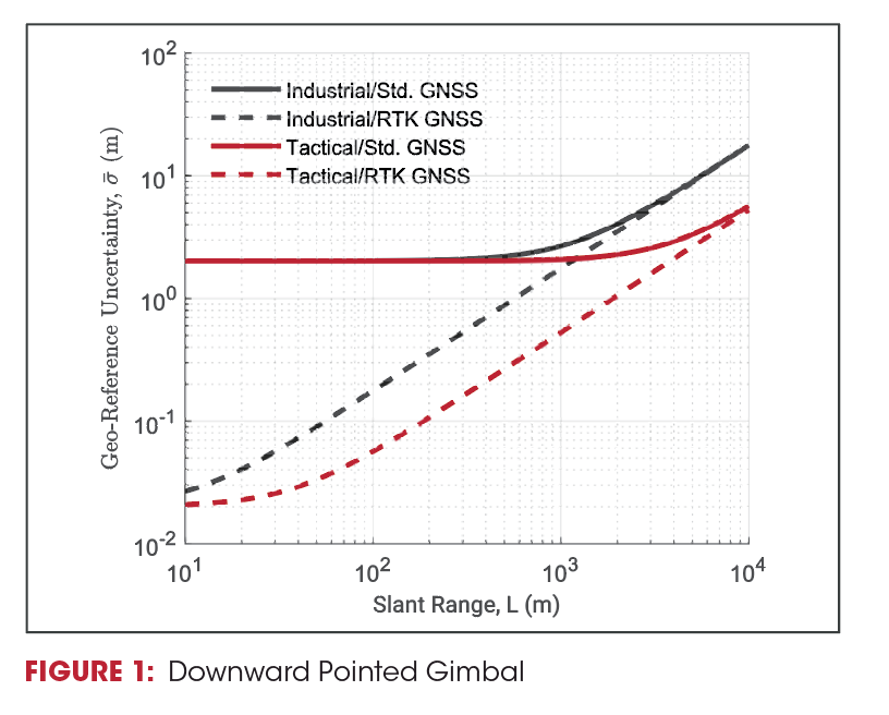
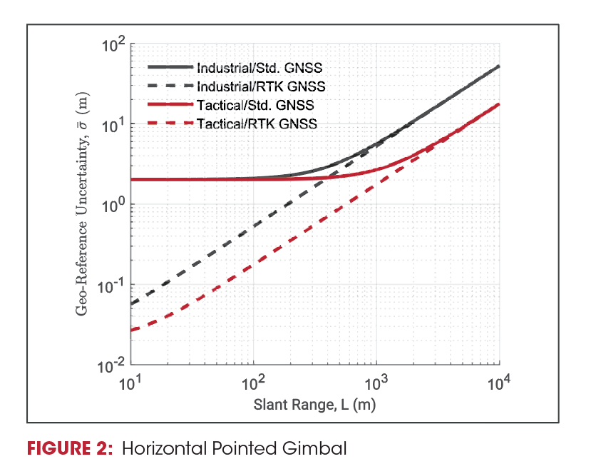
Figures 1 and 2 show the image overlay uncertainties contributions from the GNSS/INS, depending on industrial-grade vs tactical-grade inertial performance, and standard L1-only GNSS vs external RTK GNSS positioning.
Since heading accuracy is much worse than pitch/roll accuracy, Figures 1 and 2 also show the uncertainties based on whether the gimballed camera is generally downward-pointing (yaw errors negligible) or horizontal (yaw errors dominate). At short ranges (<100m), the GNSS accuracy dominates the system accuracy, whereas at long ranges (>1000m) the INS performance is determinative.
ISR SYSTEM ERROR BUDGET
The estimated pointing solution of the gimbal (˜PG) can be found by taking the offset of the feature in the camera (xˆ, yˆ, fˆ) and rotating it to a North-East-Down (NED) coordinate frame using an estimated coordinate frame transformation matrix (C) and multiplying it by the slant range (L) and adding it to the position of the aircraft (˜PA) as shown in Equation 1.
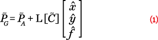
Each term in the equations is subject to different errors from different sensors. The error budget determines the contribution of all data sources—each sensor has an inherent margin of accuracy—that affect the acquired data quality, to check if the degree of uncertainty in the measurement solution meets the minimum job specifications.
An error budget quantifies all of the sources of error in a system, and accumulates them into a total system performance. By understanding how certain sources of error affect the ISR system, as well as the magnitude of those errors, total system performance can be improved through smarter design choices and error mitigation techniques.
It is useful to split errors into NED coordinate frame errors and errors orthogonal to the slant range. Direct errors in position are usually referenced in an NED coordinate frame, while errors related to attitude can be represented as perpendicular to the slant range.
For all errors related to attitude (∈ [°]), the error in position (σ¯ [m]) can be calculated as a function of some distance (d) as shown in Equation 2. This can be used to find the error perpendicular to the slant range.
![]()
GNSS/INS PERFORMANCE IMPACT
A GNSS/INS introduces a measure of error into the positioning and heading solutions for the sensor suite and its produced data. The error budget from GNSS/INS uncertainty can be split into GNSS/INS position error and GNSS/INS attitude errors.
Position errors largely reflect errors in the GNSS solution. These are caused by satellite orbit data inaccuracies, satellite clocks, receiver noise, ionospheric delay, tropospheric delay, and multipath, or reflected signals. GNSS horizontal and vertical position errors translate directly to those same errors in the pointing solution.
Meanwhile, attitude errors are largely determined by the INS. Inertial sensors are subject to several common error sources such as bias, noise density, scale factor, misalignments, temperature dependencies, and gyro g-sensitivity.
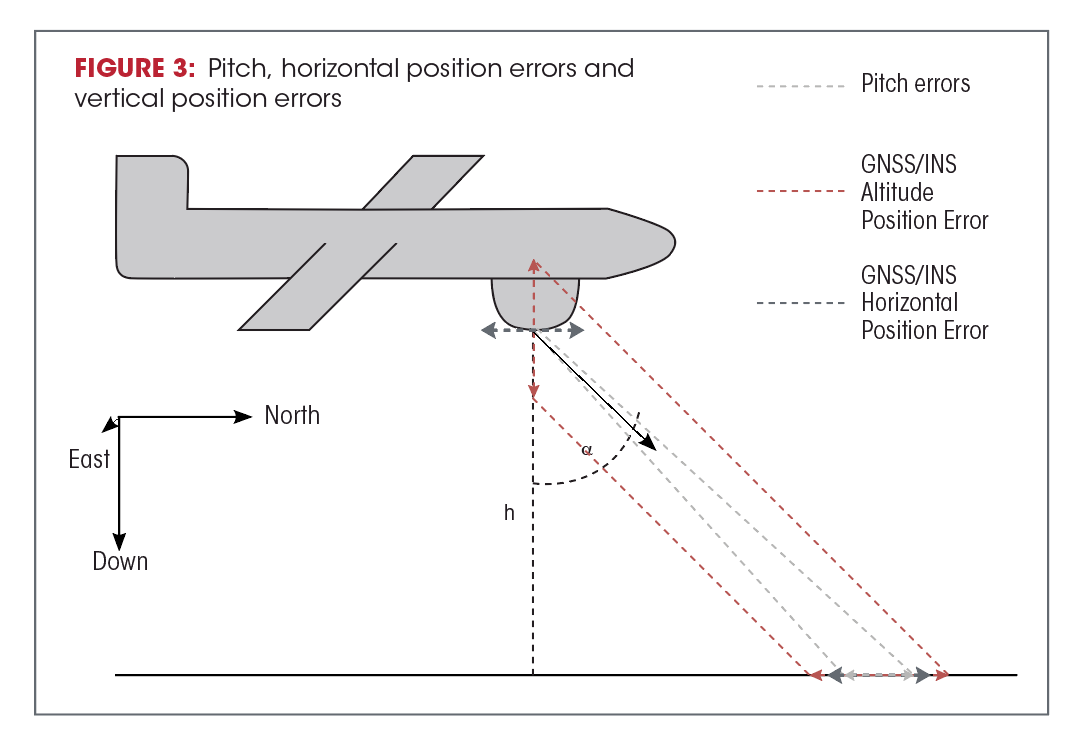
The contribution to the error budget from the attitude uncertainty can be calculated by finding the error perpendicular to the slant range. The exact translation from roll/pitch/yaw to position errors in the slant range frame (dependent on gimbal look-angle, α) can be found using Equation 2 and the values in Table 1.
Multiple sources of INS error must be accounted for when determining how much error is acceptable for an accurate navigation solution (see Figure 3).Although not described in detail here, these need to be accounted for by professional guidance in manufacturing and installing a GNSS/INS on your platform. VectorNav can provide such guidance.
OTHER ERROR SOURCES
In addition to the error contributions from the GNSS/INS, a system designer or integrator must consider a variety of other terms in the error budget, including misalignments, timing errors, and camera distortions.
Misalignments between the navigation system and the imager electronics sometimes exceed the attitude errors of the GNSS/INS system itself, and their effect can be characterized similarly attitude errors from GNSS/INS, using Equation 2 and Table 1.
Time synchronization between the EO/IR system and the GNSS/INS is also critical. Any errors in timing will be multiplied by the linear and angular velocities of the gimbal to create additional position and attitude errors.
To compensate for misalignment and timing errors, the system should be calibrated on a part-by-part basis to determine the fixed misalignment offset by comparing the measured values of the system to some independent source of truth. We recommend that this calibration take place in a benchtop testing environment during manufacturing to prevent the introduction of other error sources during the calibration.
And of course, the EO/IR system itself will have errors that must be accounted for in the error budget, ranging from intrinsic parameters that can be calibrated, like lens distortions and focal length, to limitations on accuracy due to the resolution of the imager and the performance of the image-processing algorithms.
EXAMPLE
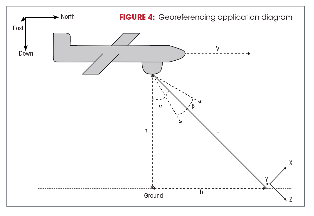
As an example of an ISR application we will look at the case where a surveying camera is mounted to a plane. Once an image is taken, a point is georeferenced using a flat and level digital elevation model (DEM) combined with gimbal attitude and position. Often, ISR applications call for mapping a point or a feature on an image to a DEM tied to a global coordinate frame (see Figure 4). This can be done by iteratively trying to find a slant range (L) such that the pointing solution aligns with the DEM.
Because we know that our georeferenced point lies on a 2D DEM the error only exists in two dimensions. In this case a plane will be traveling at 50m/s due North at a height of 1000m. Since the error budget of many of the error sources on the gimbal depend on slant range, the example will be assessed with the gimbal pointed 60 degrees directly in front of the vehicle with a theoretical slant range of 2000m. For comparing error the same configuration, GNSS/INS system, and Camera should all be used.
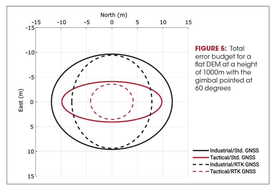
In a flat DEM the error budget from horizontal GNSS/INS uncertainty directly comes from the GNSS horizontal position uncertainty in an NED coordinate frame. For standard GNSS this gives an error of 2m in the North and East axis. The contribution from the GNSS altitude uncertainty gets projected onto the DEM as a function of the gimbal tilt angle. The position error contribution can be reduced to centimeter level by using RTK.
Figure 5 shows the overall resulting error budget, using all these calculations, for different combinations of two types of inertial sensors, industrial and tactical, and two types of GPS/GNSS technology, with and without real-time kinematic (RTK).
CONCLUSION
We have outlined the critical factors to consider in selecting an integration of inertial and GNSS equipment for your ISR application. Clearly, the calculations are complex and the results call for careful interpretation! And, every application has different requirements; aerial surveys conducted at 100 meters altitude by a small UAV rotorcraft call for a different solution than those done from 10,000 feet by a piloted airplane. VectorNav professionals can guide you through the selection and equally important installation process for your specific job. Go to www.vectornav.com to begin the process.