When Ingenuity, the little helicopter that could, sprang from the Martian surface into the wispy thin Martian atmosphere, it knocked down all kinds of firsts. The first powered, controlled flight on another planet. The first autonomous flight. The first use of an inertial navigation system and visual odometry across an alien world.
To make this happen, NASA invested $85 million to build Ingenuity, accommodate it onboard Perseverance for the long interplanetary flight and parachute deployment, and operate it once it reached distant Mars.
There’s plenty to marvel at in this undertaking, which took the fertile minds of NASA’s Jet Propulsion Laboratory (JPL), NASA Ames Research Center, NASA Langley Research Center and companies that included AeroVironment, Inc. (see accompanying feature) on a six-year journey from inspiration to realization. Awe will be confined within this article to the phenomenon of Ingenuity’s navigation system.
NAVIGATING THE SUBSYSTEMS
The Mars copter’s flight control system consists of four main subsystems: the Mode Commander, setting the overall mode for the flight control system; the Guidance subsystem, providing reference trajectories for the flight path; the Navigation subsystem, giving estimates of the vehicle state; and the Control subsystem, commanding the actuators based on the reference trajectories and the vehicle state.
The specific challenges for the navigation system onboard the UAV include:
• A lack of global navigation aids, such as GPS or a strong magnetic field.
• A large communication time lag between Earth and Mars, preventing real-time communication during flight.
• A harsh radiation environment that can adversely affect computing elements.
Because of the time-lag challenge, Ingenuity has to perform on its own. Autonomously, in other words. Radio signals from NASA Command take 15 minutes and 27 seconds to travel the 173 million miles (278.4 million kilometers) to Mars. Once on the surface, the more well-endowed Perseverance rover served as a communications relay link so the helicopter and Mission Team on Earth could communicate. It passed flight instructions from NASA’s Jet Propulsion Laboratory in Pasadena, California, to Ingenuity. From a Martian hillock 65 meters away, the four-wheeled rover observed and recorded its four-bladed offspring’s history-making flights.
While hovering on its four initial flights, the helicopter’s navigation camera and laser altimeter fed information into the navigation computer to ensure Ingenuity remained not only level, but within the borders of its 10×10 meter airfield—a patch of extraterrestrial real estate chosen for its flatness and lack of obstructions. Because landing hazard avoidance was not prioritized for this technology demonstration, each of those four initial flights began and ended within an area that had been pre-inspected and determined to be safe in terms of obstacles and ground slope.
Ingenuity conducted five flights according to its programmed lifeline across a period of 31 Earth days, or 30 sols on Mars. Then came the surprise ending-to-date, but more on that later.
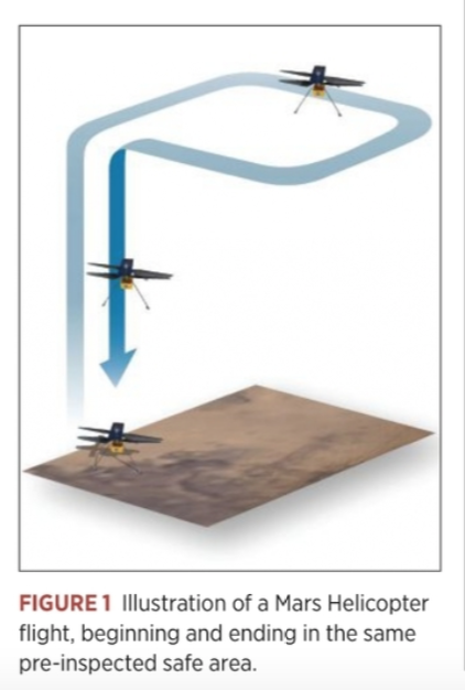
For the helicopter’s pre-arranged autonomous test flights, under the NASA rubric of “technology demonstration,” it took off, climbed, hovered, translated between a set of waypoints, then descended to land again (see Figure 1). Although the helicopter did operate independently during flight, the waypoints were specified from Earth prior to flight.
AUTONOMY?
This, however, raises an interesting and somewhat subtle point: is Ingenuity truly autonomous?
It depends on your definition. Engineers at AeroVironment, which constructed major elements of the helicopter but was not involved in the guidance, navigation and control (GNC) system design, weighed in on the issue.
“It certainly is making autonomous decisions [in managing rotor speed and pitch] to get more cyclic to overcome a wind gust,” said Jeremy Tyler, senior aeromechanical engineer. “It’s managing its altitude, it’s managing its position, all by itself without any external intervention.”
“It’s inherently unstable,” added Matt Keennon, technical lead for rotor system development. “It can’t fly for a half-second without making decisions based on the inertial measurement unit [IMU] and driving the control system.”
“There’s no [navigation] decisions being made onboard,” countered Ben Pipenberg, AeroVironment’s engineering lead on the Ingenuity project. “When Perseverance landed, it used terrain-relative navigation, and it was making decisions based on outside observable data that it was collecting without human input. That would be an autonomous system. Ingenuity is not doing that. It’s essentially using VIO—visual-inertial odometry—just to navigate over the ground in a pre-determined flight path, uploaded from Earth.”
Tyler concurred, after a fashion. “It’s doing its own simple autonomy. But certainly no sophisticated mission planning or decision-making.”
THE NAVIGATION SYSTEM
Engineers at JPL under the direction of Håvard Grip, Mars helicopter chief pilot, developed and assembled the visual-inertial navigation system emphasizing robustness, but with a correspondingly limited position accuracy and ability to navigate in complex terrain. In particular, the system assumes that features observed by the navigation camera lie on an approximate ground plane with known slope. This is why the landing field was chosen and why the first four flights did not venture beyond its bounds. The flights took place over relatively flat terrain, with short-term height variations on the order of 10% of the flight height.
The navigation sensors Ingenuity carries are:
• Bosch Sensortech BMI160 IMU, for measuring 3-axis accelerations at 1600 Hz and angular rates at 3200 Hz.
• Garmin Lidar-Lite-V3 laser rangefinder (LRF), for measuring distance to the ground at 50 Hz.
• Downward-looking 640 x 480 grayscale camera with an Omnivision OV7251 global-shutter sensor, providing images at 30 Hz.
• MuRata SCA100T-D02 inclinometer, for measuring roll and pitch attitude prior to flight.
All are commercial off-the-shelf (COTS) miniature sensors, largely developed for the cell phone and lightweight drone markets.
Ingenuity also carried a second camera, a 13-megapixel color camera with horizon-facing view for terrain images, not used for navigation.
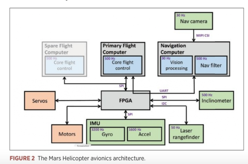
Figure 2 shows Ingenuity’s avionics system architecture. A radiation-tolerant field-programmable gate array (FPGA) function routes sensor data and traffic between other computing elements and performs low-level actuator control. Most of the flight control software is hosted on the flight computer (FC).
A separate navigation computer (NC), a 2.26 GHz quad-core Qualcomm Snapdragon 801 processor, provides the throughput for vision-based navigation. On the NC, one core is devoted to camera-image processing and another to the navigation filter, while the remaining cores are used for other activity.
The visual-inertial navigation system provides the control system with real-time estimates of the vehicle state: position, velocity, attitude and angular rates. The state estimate is based on fusing information from the onboard IMU, inclinometer, LRF and navigation camera.
HEAD TO THE CHOPPER
“Before each of Ingenuity’s test flights,” Grip told Inside Unmanned Systems, “we uploaded instructions describing precisely what the flight should look like. But when it came time to fly, the helicopter was on its own and relied on a set of flight-control algorithms that we developed here on Earth, before Ingenuity was even launched to Mars.”
When the copter rests on the ground, preparing to take off, the inclinometer estimates initial roll and pitch attitude. Based on this, initial estimates of the accelerometer and gyro biases are also obtained.
Once the vehicle is in motion, integration of the IMU measurements is used to estimate changes in position, velocity and attitude. Only the IMU is used for this critical second, measuring acceleration and angular rates. After the helicopter reaches 1 meter off the ground, the laser rangefinder and downward-looking camera are added to the navigation solution. This precaution springs from pre-mission concern that the LRF and camera might be obscured by dust kicked up by the copter blades. The IMU will not output great accuracy in the long-run, but because Ingenuity takes only a couple of seconds to reach 1 meter, “we can make it work,” Grip said. Ingenuity then starts using its full suite of sensors.
During hover flight, Ingenuity on its semi-autonomous own attempts to maintain a constant altitude, heading and position. The JPL team has to rely on the copter’s estimates on how well it performs this task, as there is limited to no basis for ground truth. But the available data shows that Ingenuity holds its altitude extremely well in hover, to within approximately 1 centimeter, and its heading to within less than 1.5 degrees. Horizontal position can vary up to approximately 25 centimeters, which the team attributes to wind gusts on the Red Planet.
CRUISE CONTROL
Because of the relatively low accuracy of MEMS-based IMUs, navigation aids must bound the growth in navigation errors as the copter cruises. The LRF provides range measurements between the vehicle and the terrain below, giving vertical velocity and position. With the aid of the MaVeN feature-tracking algorithm, the navigation camera tracks visual features on the ground, under the assumption that all features are located on a ground plane with a known slope. This provides horizontal velocity as well as roll and pitch attitude, and helps limit the drift in horizontal position and yaw angle.
However, the latter two measurements have no absolute reference, and their estimates are subject to long-term drift. Therefore, shortly before touchdown at the end of each flight, a navigation camera image is stored for later transmission on Earth, so that an absolute position and heading fix can be obtained by comparison to the known terrain.
“To develop the flight control algorithms,” Grip wrote in a NASA blog post updating Ingenuity’s fans, “we performed detailed modeling and computer simulation in order to understand how a helicopter would behave in a Martian environment. We followed that up with testing in a massive 25-meter-tall, 7.5-meter-diameter vacuum chamber here at JPL, where we replicate the Martian atmosphere. But in all of that work, we could only approximate certain aspects of the environment. Now that Ingenuity is actually flying at Mars, we can begin to assess how things stack up against expectations.”
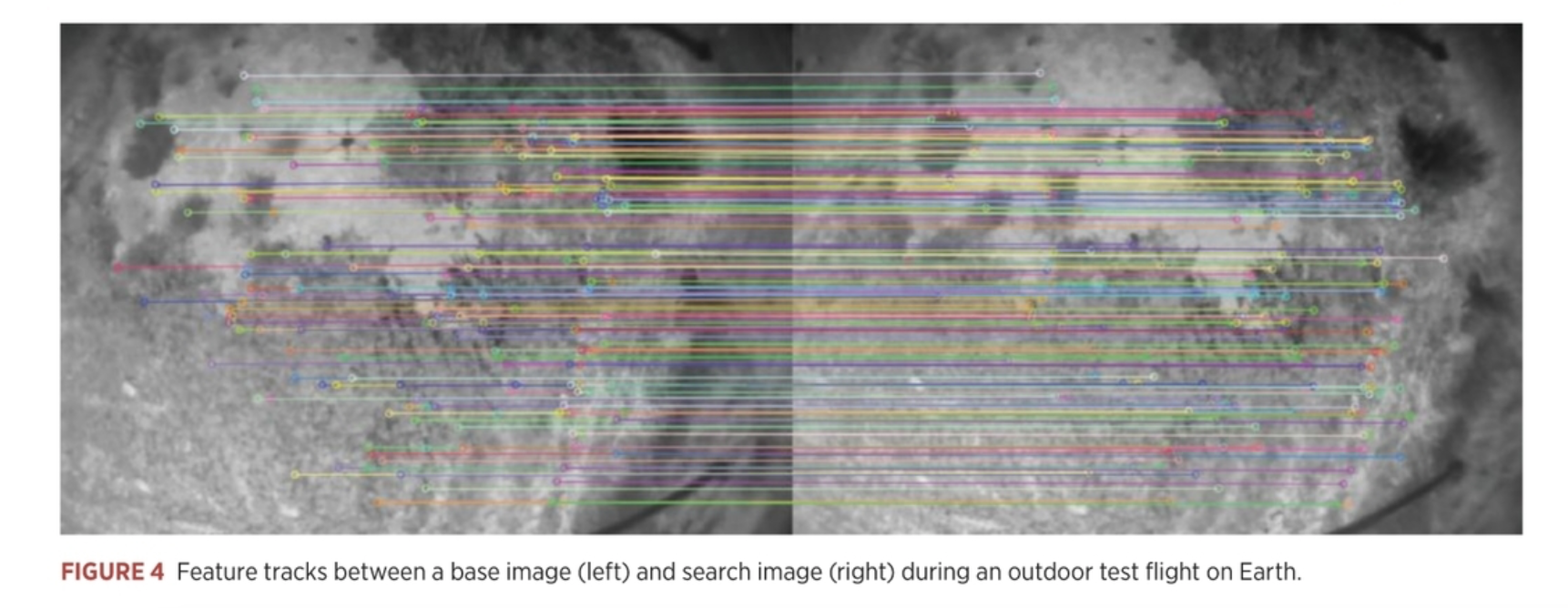
The MAVeN navigation algorithm used “has no absolute references to any landmarks,” according to Grip. “It always operates against a base frame where it sees a bunch of features and tracks them over a limited set of search frames. When it’s done, it requires a completely new base frame. It is always tracking in a relative sense, never tied back to a global frame.
MAVeN is implemented as an Extended Kalman Filter (EKF) that also uses the difference between the predicted and measured LRF range. MAVeN has a state vector with seven components: position, velocity, attitude, IMU accelerometer bias, IMU gyro bias, base image position and base image attitude, for a total of 21 scalar components.
MAVeN only tracks features between the current search image and the base image. Because the base frame is frequently reset as features are lost, MAVeN is effectively a long-baseline visual odometry algorithm: the relative position and attitude between the two images are measured, but not the absolute position and attitude. Absolute position and attitude error, in this case horizontal position and yaw, grow over time. The LRF provides vertical position, which bounds vertical position error. In addition, the visual features and flat-plane assumption provide observability of absolute pitch and roll when the vehicle is moving.
A key advantage of MAVeN over other simultaneous localization and mapping (SLAM) algorithms is that the state only needs to be augmented with six scalar elements—three for position and three for attitude. The LRF and an assumed ground plane enable MAVeN to estimate 3D position and velocity without introducing a scale ambiguity.
The two main disadvantages of MAVeN are sensitivity to rough terrain, due to the ground-plane assumption, and long-term drift in position and heading. For Ingenuity’s technology demonstration phase, this is an acceptable tradeoff, because accuracy degradation is graceful and the algorithm has proven to be highly robust in both simulation and experiments.
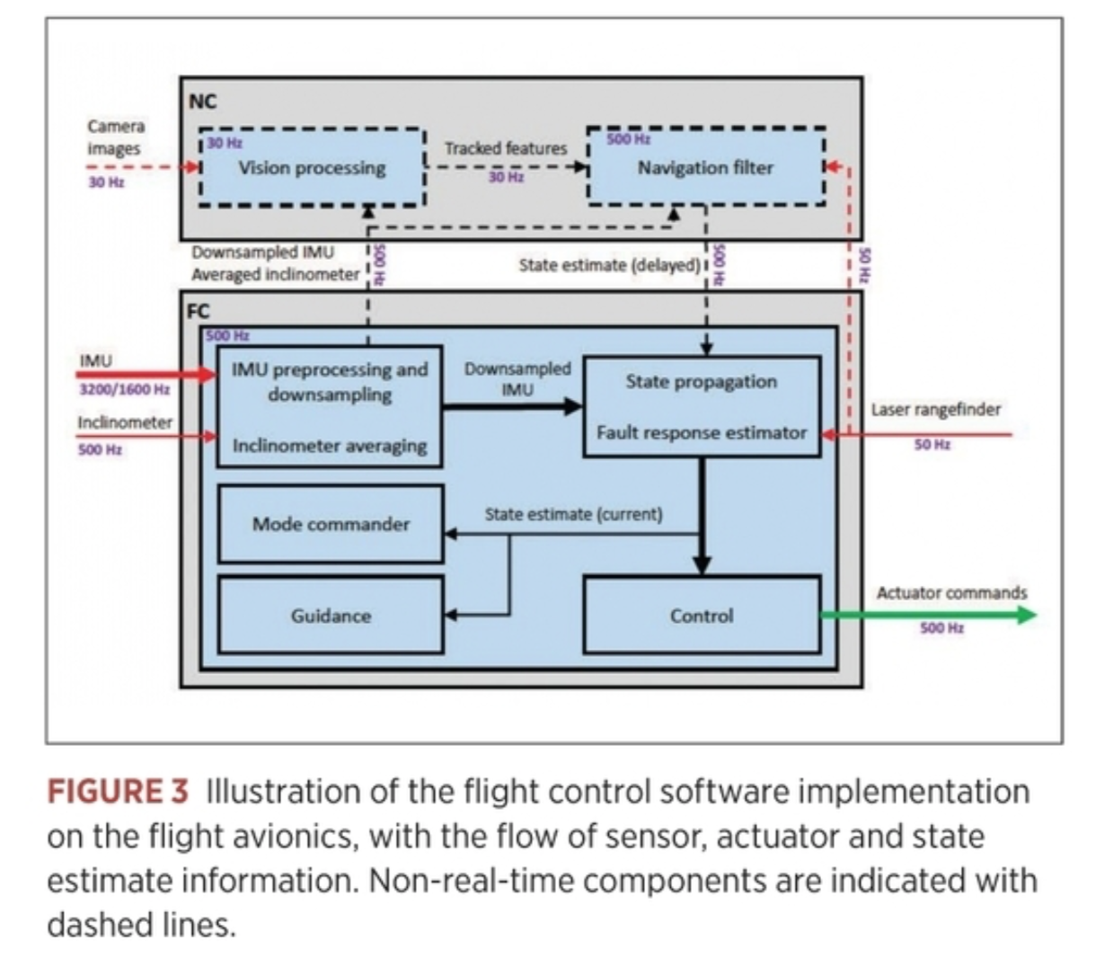
Feature detection in base images is performed with an implementation of the FAST algorithm [30], which selects corner-like features that have sufficient contrast between a center pixel and a contiguous arc surrounding the center pixel. An algorithm estimates the displacement of a template from one image to the next, using a gradient-based search algorithm that minimizes the difference in pixel intensity (see Figure 3).
BRINGING IT ALL BACK HOME
Landing is an altogether delicate matter.
A rapid sequence of events takes place as Ingenuity descends toward the ground. “First, a steady descent rate of 1 meter per second is established,” Grip wrote. “Once the vehicle estimates that the legs are within 1 meter of the ground, the algorithms stop using the navigation camera and altimeter for estimation, relying on the IMU in the same way as on takeoff. As with takeoff, this avoids dust obscuration, but it also serves another purpose: by relying only on the IMU, we expect to have a very smooth and continuous estimate of our vertical velocity, which is important in order to avoid detecting touchdown prematurely.
“About half a second after the switch to IMU-only, when the legs are estimated to be within 0.5 meters of the ground, the touchdown detection is armed. Ingenuity will now consider touchdown to have occurred as soon as the descent velocity drops by 25 centimeters per second or more. Once Ingenuity meets the ground, that drop in descent velocity happens rapidly. At that point, the flight control system stops trying to control the motion of the helicopter and commands the collective control to the lowest possible blade pitch to produce close to zero thrust. The system then waits 3 seconds to ensure the helicopter has settled on the ground before spinning down the rotors.”
The downward-facing camera takes several images on landing, which is factored into the sequence for next takeoff.
SURPRISE ENDING
Ingenuity’s planned technological demonstration was to last for five flights. Then, sadly, its pathbreaking life would come to an end, its duty done. Its parent and ride to Mars, the four-wheeled Perseverance rover, would continue for two more years to explore the Jezero Crater, site of a lake 3.9 billion years ago, seeking traces of ancient microbial life. Ingenuity would perch motionless forever upon the Martian landscape, the lonely one.
But wait.
“On the last flight, we actually flew somewhere else,” Grip said. “We had scouted that terrain previously with the helicopter.
“In that scouting flight, No. 4, we took images using the high-resolution return-to-Earth color camera. We could see on our target airfield, individual rocks, ripples, features, that we then georeferenced against a low-resolution satellite image, so we knew exactly where those features were in a global frame. When we went back on flight 5, we could use those features to reference ourselves.”
Flight No. 5’s landing looked great, as good as it could have been. Everything went according to plan.
Then a momentous decision was made in Pasadena, to send Ingenuity further—into an operational demonstration phase, very different, at a lower cadence for helicopter operations. As the Mars Project focuses now on rover Perseverance and the science it delivers, “We’re in a background role,” Grip said, “doing flights every two to three weeks, to demo operational capability, at higher risk, and focused more on aerial imaging capabilities.
“These flights are stretching Ingenuity’s capability in terms of altitude, distance and speed. We’ve covered our basics, shown that a helicopter can fly on Mars, nicely and confidently. We’re now stretching the parameters of those flights with the hardware and software that we have on the helicopter.”
The increased speed over ground affects the navigation system and how the features the camera is tracking move through the field of view. Additionally, new flights will break the parameter of flying over relatively flat terrain. “We may fly over less flat terrain, that will challenge the navigation algorithm. How less flat is not factored in an explicit way. We can look at the LRF data after the fact and analyze it, but it’s not being used in real time to navigate the copter.”
“As we continue with our flights on Mars,” Grip concluded, “we will keep digging deeper into the data to understand the various subtleties that may exist and would be useful in the design of future aerial explorers. But what we can already say is: Ingenuity has met or exceeded our flight performance expectations.”