Vision-Based Collaborative Navigation for UAV-UGV-Dismounted Units in GPS-Challenged Environments
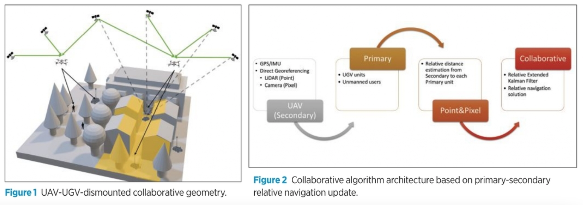
A collaborative navigation scenario between manned and unmanned systems operates in a GPS-challenged or -denied ground environment, driven by a UAV flying above with access to GPS signals. The architecture provides relative position, velocity and attitude to the ground units, manned and unmanned. During GPS outages, the UAV’s vision sensor detects and tracks features, and inertial drift is bounded by external measurements.
by Shahram Moafipoor, Lydia Bock, Jeffrey A. Fayman, Eoin Conroy and Bob Stadel, Geodetics Inc.
Today’s mission-critical defense applications on land, air and at sea depend on accurate, assured PNT (A-PNT) or resilient PNT. The large diversity of platforms in contemporary defense systems demand unique and tailored solutions that bring together sensors and emerging technologies in novel ways. As current and emerging threats can deny or degrade GPS access, there is an urgent need to develop robust autonomous navigation theories, architectures, algorithms, sensors and, ultimately, systems that provide assured GPS-level PNT performance in all environments, independent of GPS.
Currently, there is no “silver-bullet” system that can replace the capabilities provided by GPS. Alternatives are platform/application specific in their solution.
This article presents a collaborative navigation scenario between manned and unmanned systems: several UGVs and/or dismounted soldiers operating in a GPS-challenged or -denied environment and UAVs flying above the environment with access to GPS signals, as shown in Figure 1. This enables the ground-based platforms to navigate without GPS by taking advantage of the overflying UAV’s access to GPS and the relative position, velocity and attitude between the UAV and ground units.
SYSTEM SPECIFICS
Each independent platform has its own complementary navigation module, but, as a team, they share their common resources and cooperate to address common navigation goals. The collaborative navigation relies on data flowing from the UAV to the individual UGVs and dismounted soldiers, which are integrated in a relative extended Kalman Filter (EKF) where the UAV is denoted “secondary” and the ground units are denoted “primary.”
The system can support a single secondary, which covers a predefined area, and multiple primary units connected via datalink to the secondary unit. Processing is performed in the primary unit for each primary/secondary pair individually. The secondary unit (UAV) used in this study was instrumented with a payload consisting of GPS/IMU/tactical LiDAR/RGB camera and a datalink for communications with the primary units. The primary units (UGVs and dismounted soldiers) were all instrumented with a processing unit and GPS/IMU sensing module.
The core of the system is a relative EKF, which uses IMU measurements of the primary and secondary units to establish the relative inertial navigation states as the prediction model. The relative observation model is used to update the relative navigation solution and calibrate the primary IMU. Typically, the relative observation is provided by differential GPS processing between primary/secondary pair, but in this study the relative position was generated by the vision sensor on the secondary unit rather than GPS in order to simulate GPS-denied conditions for ground units.
In this approach, the vision sensors provide relative measurements between the secondary (UAV) and primary (UGV/dismounted soldiers). By using the relative EKF, the relative observation between the primary and secondary is also used to remotely calibrate the primary’s IMU (see Figure 2).
As the primary units are either vehicles (UGVs), and/or people in (e.g. dismounted soldiers), in order to measure the relative distance between the secondary and primary from the vision sensors, these features must be detected and tracked from the secondary unit in a model-free manner. Several approaches can be considered including:
- LiDAR-only.
- LiDAR/camera (point & pixel) in the form of colorized LiDAR point clouds.
- Mono-RGB or thermal supported by a LiDAR-based digital terrain model (DTM).
- Dual-camera stereo configuration.
To handle the large amount of LiDAR and image data associated with these approaches in a reasonable processing time, improvements were made to several aspects of previously existing algorithms. These were done to overcome size limitations of LiDAR and camera data, to improve the efficiency of the automated data segmentation and to provide a robust solution for feature-of-interest detection.
The RGB camera-only approach, despite many advantages, has the shortcoming of useful operational time (day-night restrictions) and is therefore not addressed. Thermal imaging is an interesting alternative as it can be implemented equally well day and night and because it is sensitive to objects’ thermal signatures. However, the main restriction with using these cameras is the small sensor size (e.g. 640×512 pixels), which inhibits use over extensive areas. One way to overcome this restriction is to mount the system on a gimbal; however, in our multi-sensor integration, this approach is not feasible as the LiDAR/camera are directly georeferenced in real time, enforcing a solid geometry between components.
For these reasons, here we focus on the first two approaches for feature detection and tracking: LiDAR-only and LiDAR-RGB camera (point & pixel).
UAV-BASED LIDAR SENSOR ONLY
LiDAR sensors can be classified into three categories: multi-beam tactical, solid-state LiDAR and single-beam aerial scanners. Here we use multi-beam tactical grade LiDAR sensors, as the other two categories are redundant for our application due to a narrow field of view (FOV). From use in autonomous driving systems, rich algorithms have been developed for rapid feature detection and tracking. However, we found that the signature of features from UAV-based LiDAR sensors looking down from the platform are entirely different from typical autonomous driving systems, in which the LiDAR is oriented for horizontal scanning and the environment is scanned in full circle (360°).
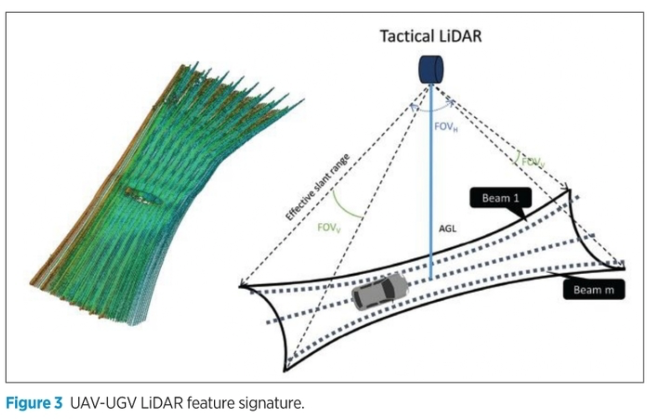
The other challenge is point-cloud resolution. A multi-beam tactical LiDAR sensor typically scans an area with 360° horizontal FOV and 20-40° vertical FOV, as shown in Figure 3. While the horizontal angular resolution can be as high as 0.1°, the vertical FOV is usually larger. A tactical-LiDAR sensor commonly has 8–64 channels (beams) with a vertical angular resolution of 1–2°. One can estimate the resolution by dividing the number of beams over the span of the vertical FOV.
In new scanners, the laser channels are not emitted in a symmetric pattern. Rather, they are concentrated more along the center to optimize vertical angular resolution. The projection of the horizontal angular resolution to the ground can determine the along-track resolution, and the across-track resolution is derived by projecting the vertical angular resolution to the ground. These definitions are critical, as we need to confirm having enough along-track and across-track resolution to detect features of interest.
A combination of along-track and across-track resolution is defined as the footprint size of features (or, simply, resolution). For UAV-based systems, the signature of features is primarily influenced by the across-track resolution, which is a function of flight altitude and speed. Figure 3 shows this signature for a car captured with a tactical-level UAV-LiDAR, acquired over a full cycle of m-beam scanning. This angular resolution, denoted FOVV in Figure 3, can project up to 0.5 m across-track resolution at a low flight altitude. This across-track resolution may be large enough to detect vehicle features, as shown in Figure 3 for one epoch of LiDAR scanning data.
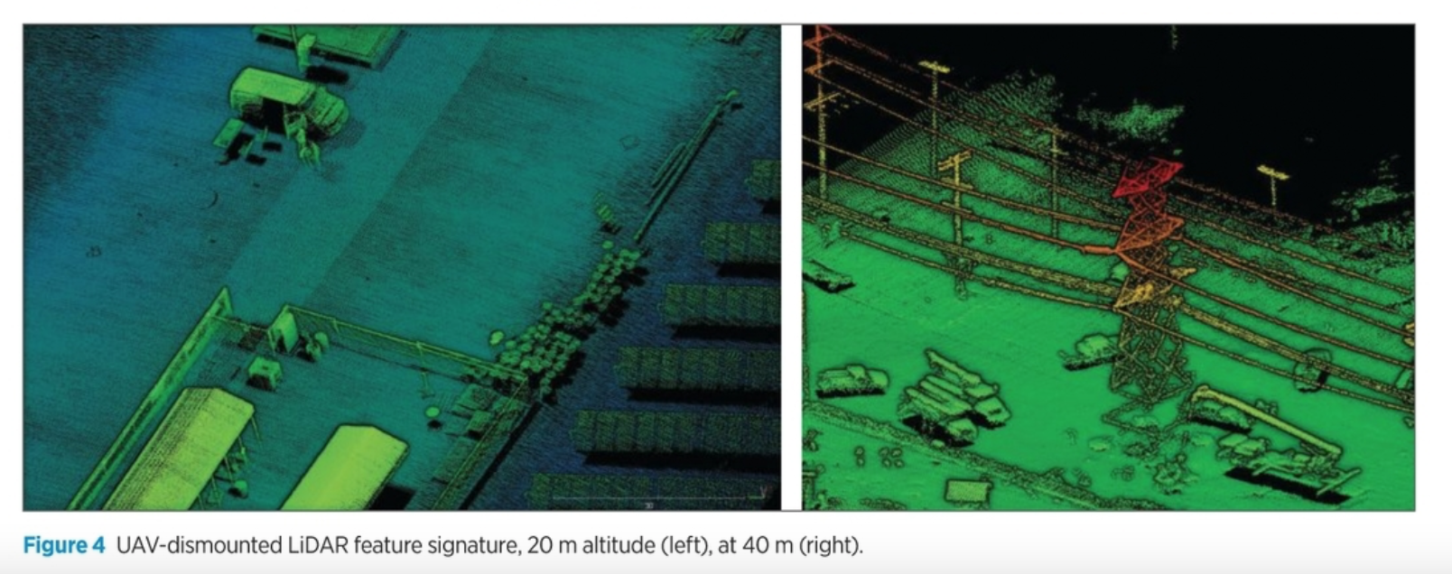
Unlike UGV-signatures, human body detection from the air can be challenging with tactical grade LiDAR sensors, as the footprint size of LiDAR point clouds is typically lower at high flight altitudes. As an example, in Figure 4 (left), by flying at a 20 m altitude at a speed of 3 m/s, a tactical LiDAR can provide point clouds up to 7 cm along-track resolution, which is adequate for human body detection; this number will be doubled for a 40 m flight altitude, as shown in Figure 4 (right), making it more challenging to detect human bodies even with supervisory techniques. This low resolution can be critical, as people, unlike vehicles, typically move in a tight group, separated by minimal distance.
In the LiDAR-only approach, our algorithm for feature vehicle/human identification begins with extracting elevated points from individual scanlines and clustering them. However, this single criterion does not facilitate successful feature extraction in complex environments. Therefore, additional criteria were applied to form an automatic feature extraction system.
The modifications were inspired by algorithms developed in machine-learning fields. With this approach, vehicle tracking is based on detecting regions of interest, removing the ground surface, clustering, and tracking a bounding box around each feature of interest. These steps were applied in a different order in our analog approach. Further testing using machine learning techniques showed that operators identifying features look for items that are:
- Elevated with respect to the grid surface.
- Rectangular in shape in varying size for different feature types.
- Longitudinally and vertically positioned for different feature types.
- Do not interfere with other features.
- Have appropriate size.
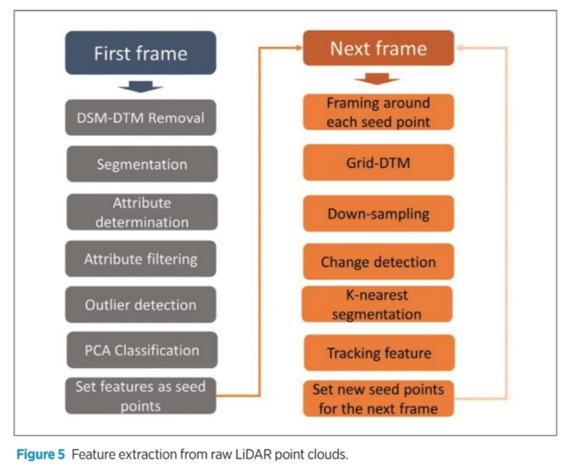
Figure 5 summarizes the implemented algorithm. It includes two phases, detection and tracking. The algorithm begins with robust detection of features. To speed up scanning, the elevated points were simply cut out by subtracting a low-order plane, fit to the grid surface in each segment. Then, clustering of peak points is performed based on criteria such as distance and angle. The process is followed by a detailed analysis of candidate targets to finally identify the points as a feature (vehicle/person).
The last feature-identification step is detection and removal of non-feature objects from extracted feature candidates. In addition to object attributes such as length and volume, non-feature objects might be detectable by exploiting intensity data.
IMPLEMENTATION
This algorithm must be fully implemented from the first frame. Once the features are identified, the algorithm is simplified to rules for tracking. The tracking filter uses constant velocity, constant elevation and constant turn models simultaneously to generate a tracking solution. In the case of multi-features, this algorithm runs individually for each seed object. In this case, a new unit is removed from the solution and/or re-entered, and the algorithm starts over.
The key difference in the implemented algorithm and existing deep-learning algorithm is in the scale of perception of environment. In autonomous driving, the LiDAR scans the surrounding environment in a large area, from which it is easy to develop a prediction model for individual features that last until they are past the autonomous vehicle.
However, with a UAV, features seen on the ground exist within a narrow field of view, which requires extension of the architecture to a swam of UAVs.
Most of the challenges discussed are associated with UGVs, as the dismounted units travel over a smaller scale. In addition, there are more challenges with human detection when operating from higher altitudes. In future work, a thermal camera is considered to augment the sensor configuration for improved detection and tracking of humans.
UAV LIDAR/CAMERA POINT & PIXEL
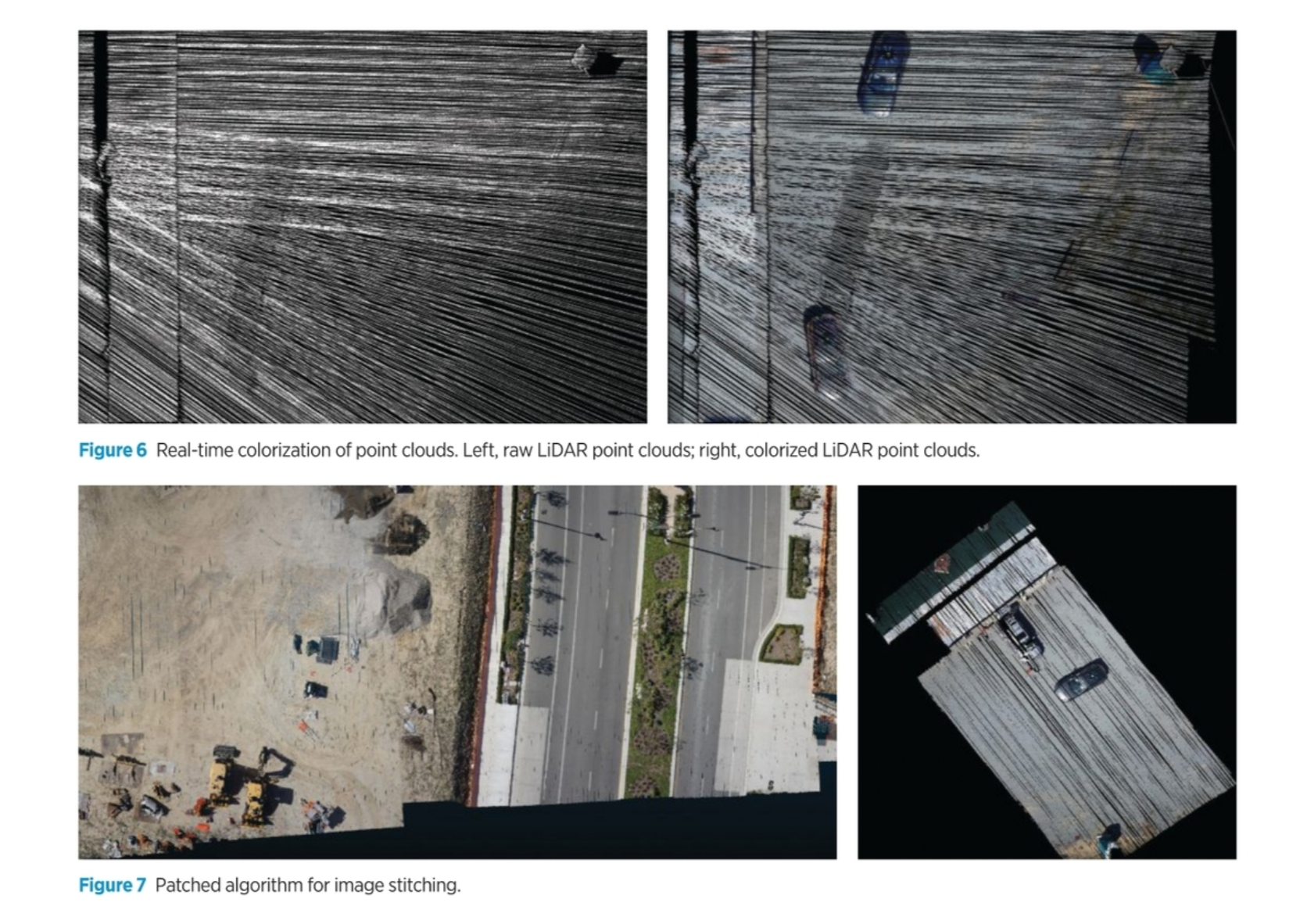
In the Point & Pixel approach, the camera is used for colorization of the LiDAR point clouds. This colorization adds an additional dimension to the point clouds, which facilitates quicker detection of features using RGB-color segmentation.
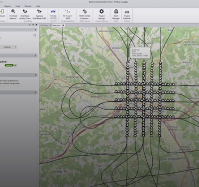
Figure 6 shows the raw LiDAR point clouds (left) and the colorized point clouds (right), in which the features are more visible for detection and classification. The conventional technique for colorizing LiDAR point clouds is to merge two layers of information: geo-referenced point clouds and a Geo-TIFF orthomosaic image. To generate an orthomosaic, the scan area must be covered by a survey grid such that the images are captured with high overlap and sidelap to provide strong geometry for use in the aerotriangulation process.
The main challenge in colorizing LiDAR point clouds is in generating the orthomosaic subject to parameters that may not be available for many mapping conditions, including real-time mapping.
Knowing the accurate position and attitude of captured images, one logical approach is to rectify images and use the orthogonal image for colorizing images. In implementation, one must carefully compensate for the camera’s interior calibration parameters, camera boresight and any possible time-tag latency.
Once these parameters have been accounted for, we still observe random colorization errors. Further study found that the camera is more sensitive to exposed vibrations of the UAV during data acquisition than the LiDAR sensor. Several hardware and software modifications were made.
Starting from hardware, each UAV has a unique vibration signature, which requires damper designs sufficient to denoise unexpected vibrations. Unaccounted-for vibrations cause many issues, from mechanical fatigue, which can wear out fragile parts and electrical components prematurely, to IMU sensor reading outputs, blurring the captured imagery and fanning effects displayed on LiDAR sensor measurements and subsequent point clouds.
From the software perspective, the main challenges were in developing an area-based patching algorithm for image stitching, and in the use of key point features between the LiDAR point clouds and the images in each patch for control registration. This process is followed by detection/rejection of out-of-order images in each patch and finally color-balancing across the images. Figure 7 shows the final solution for single image and over an area covered with multiple images.
To use the geo-referenced colorized point cloud, we experimented with interpolating/extrapolating the irregular colorized point clouds to a regular grid and treating it as a 2D range image (raster based). In this case, each point carries a depth value, laser intensity and RGB pixel values. One advantage of representing the point clouds in the raster form is that they can be treated as images. Thus, a range of photogrammetry/computer-vision image-processing tools and techniques can be applied to detect features of interest from them.
DATA DEMONSTRATION
We evaluated the performance of the collaborative navigation system on real-world data. A UAV instrumented with a payload consisting of GPS, MEMS IMU, LiDAR (tactical 8-channel) and an RGB camera (Sony 6000) was flown over an area where several vehicles/people were operating.
 All sensors were precisely synchronized to the GPS/IMU navigation solution. The LiDAR data was time-stamped and recorded internally, and the camera images were precisely time-tagged and geo-tagged during the process. For UGV detection, a UAV-UGV pair was operated over an open area; for the UAV-dismounted user, a person was walking in the area.
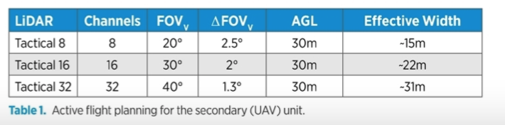
For both tests, the UAV was flown at 30 m flight altitude (AGL) and 3 m/s velocity. To ensure the UAV and primary units are visible from the vision sensors on the UAV, precise flight-planning considering the requisite overlap area is required. We found this overlap area is a function of the relative speed between the UAV and UGV/ humans and the effective swath width on the ground. Table 1 summarizes effective swath coverage for a moving UAV to cover the area with interest secondary units.
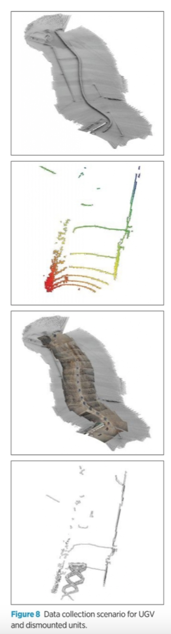
By flying at 3 m/s, the swath is increased to ~18 m when using the Tactical 8 and ~25 m for Tactical 16 LiDAR configurations. These considerations allow precise flight planning for the UAV with respect to the UGV. Figure 8 shows the UAV and UGV trajectory. The GPS outage was simulated after the first loop.
RELATIVE NAVIGATION SOLUTION
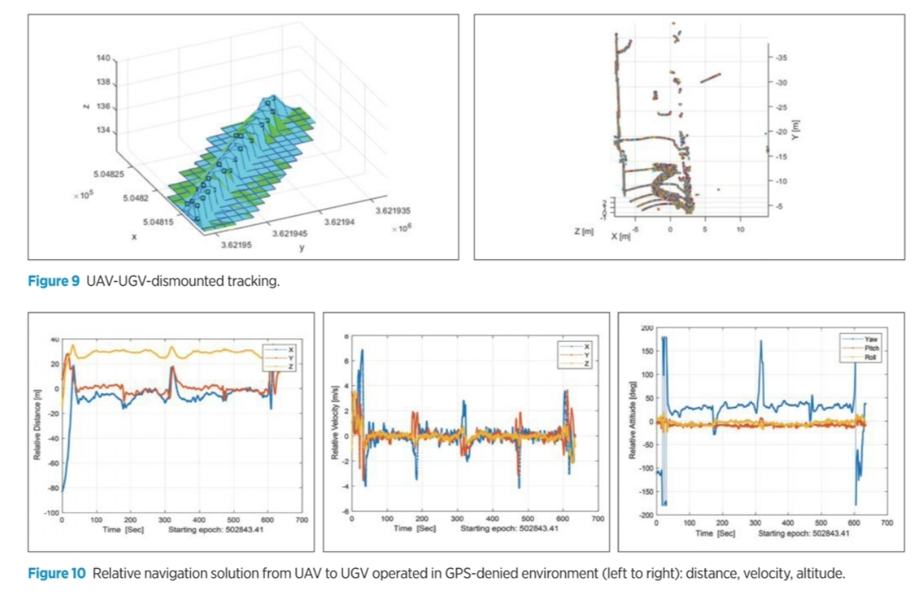
Figure 9 shows a sample of the detected and tracked features, using the described algorithm.
Each feature of interest was considered a primary unit, and the relative position derived from the secondary unit was used in the relative navigation filter for each pair. Figure 10 shows the relative navigation solution derived from the collaboration of the UAV-UGV case.
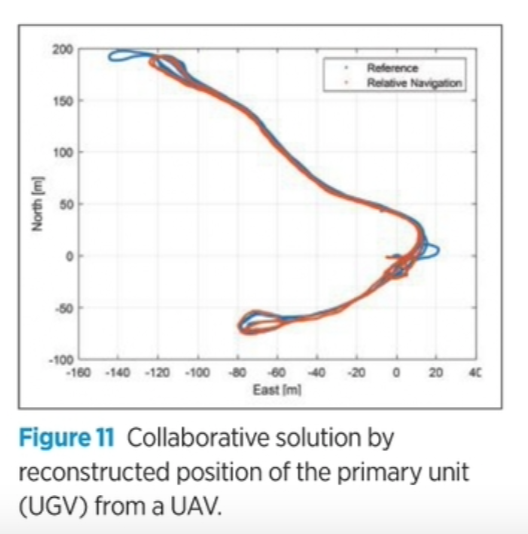
Once the relative navigation solution is provided, the absolute primary navigation solution can be determined by integrating the relative solution to the absolute navigation solution of the secondary. Results in Figure 11 show improved navigation performance when utilizing the relative observations during GPS outages. Specifically, the drift of the INS solution is bounded by the external measurements provided by the relative EKF and the tracking filter when GPS is unavailable, maintaining the desired performance in GPS adverse conditions.
The relative EKF can relax the requirement for frequent updates of the system. If the architecture is simply based on retrieving the primary units by adding the relative position from the primary to the secondary, the system is vulnerable when no position update is available. However, by remotely calibrating the IMU of the primary unit, the primary relative navigation solution can still be estimated, which can coast independently as the navigation solution. This capability also allows reduction of the update rate to less than 1 Hz.
Test results show that the collaborative navigation solution between UAV and UGV-dismounted users can improve navigation and environmental monitoring in challenging environments.
CONCLUSION
The algorithms that enable collaborative navigation systems operate across multiple platforms, including UAV/UGV/dismounted warfighters. The collaborative navigation allows primary units, UGV/unmanned soldiers, to leverage information from their onboard sensors in addition to shared data from the secondary UAV to achieve highly accurate navigation performance in all conditions, even in areas where GPS information is unavailable.
The collaborative navigation is executed in a three-layer modular approach for data fusion: UGV/dismounted feature extraction from vision-sensors in LiDAR only, or point (LiDAR) & pixel (camera) combination; feature tracking using a dynamic model; and relative extended Kalman Filter used to retrieve the primary navigation solution (position, velocity and attitude) based on the secondary unit.
The challenge lies in managing the large volume of LiDAR-camera data to sort through the data to extract features of interest and continuously track them to measure the relative position between them. By sharing relative positioning information, geo-referenced LiDAR point clouds, geo-registered imagery and other navigation data on individual platforms, the collaborative navigation system will improve overall navigational accuracy.
The collaborative scenario can extend to other applications, such as UAV-based security and autonomous driving systems.
A more practical approach for future studies would be in developing a network (swarm) of secondary units. In this case, the collaborative architecture will turn to a 4D problem. Each UAV node covers a specific area, and when a primary node makes an inquiry, it must first perceive the environment. The inquiry is responded to by the neighbored secondary nodes. The inquiry can be related to contingency events (its position, target determination, target tracking, etc.). Developing a collaborative algorithm over a network requires a distributed data fusion algorithm, which should still meet real-time or near-real-time computing constraints, independent of the network propagation delay.
ACKNOWLEDGMENTS
An earlier version of this article appeared as a paper at ION GNSS+ 2020 Virtual and is available at ion.org/publications/browse.cfm. Geodetics Inc. is an AEVEX Aerospace Company.
AUTHORS
Shahram Moafipoor is a senior navigation scientist and director of research and development at Geodetics, Inc. He holds a Ph.D. in geodetic science from The Ohio State University.
Lydia Bock is the president, co-founder and chief executive officer of Geodetics Inc. She has 35+ years of industry experience, including positions at SAIC and Raytheon. She holds a Ph.D. in engineering from Massachusetts Institute of Technology and has won the Raytheon’s Micciolli Scholar award and The Ohio State University Distinguished Alumni Award.
Jeffrey A. Fayman is vice president of business & product development at Geodetics. He holds a Ph.D. in computer science from the Technion-Israel Institute of Technology.
Eoin Conroy completed his M.Sc. in geographical information systems and remote sensing at Maynooth University in Ireland. He focuses on Geodetics’ LiDAR and photogrammetric mapping projects.
Bob Stadel serves as vice president for AEVEX Aerospace. He is a graduate of the Naval Nuclear Power Program and holds an MBA from the University of Utah.