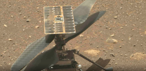
Early rotor test on the Mars surface. Photo courtesy of NASA/JPL-Caltech/ASU.
As of Friday, April 30 (local time), the Ingenuity Mars Helicopter had completed its fourth successful flight, exceeding expectations and moving from being a technical to an operational demonstrator.
In Part One of “Inside Ingenuity with AeroVironment—Designing It,” key personnel from the company talked about designing and developing Ingenuity’s airframe and some of its major subsystems, including its rotor blades and hub and control mechanism hardware. They also discussed how AeroVironment worked with JPL, Lockheed Martin and others to integrate its work into a vehicle capable of reaching and operating on Mars.
Now, in Part Two—”Challenges Overcome”—the engineering team recalls surmounting obstacles so Ingenuity and its 4-foot rotor blades could master the ultra-thin atmosphere of the red planet.
Comments have been edited and reordered for clarity.
Jeremy Tyler [senior aeromechanical engineer, with AeroVironment for 14 years, significant mechanical design work for most of the metal and plastic components: servos, linkages, swashplates, landing gear, hinges, springs, latches]
Thermal expansion was a huge challenge. The operating temperatures on Mars are extremely cold, generally, but they’re also very widely varying—it could be negative 100 Celsius, or it could be positive 20 Celsius.
But even that isn’t the full range. Every component of the helicopter had to be completely disinfected. For simple things, we could wipe them down or soak them in alcohol. But there were a number of components that wasn’t suitable for; for example, partially assembled structures, that might be damaged by alcohol, in which case we had to bake them in an oven. And so we had very high temperatures that the things had to survive, while also being able to withstand the low temperatures of service. And so it was a unbelievable range of requirements.
Also, a large portion of the purpose of the Perseverance mission is to look for signs of past life. And this is probably the most critical Mars mission so far in terms of biological cleanliness when it arrives. So, that was a huge hurdle—every component had to be designed to be cleanable; every captured space on every captured component had to be accessible, such that it could be thoroughly disinfected. Even from the mechanical design, we had to figure in disinfecting—a big challenge.
Matt Keennon [AeroVironment technical lead for rotor system development and an AeroVironment principal electrical engineer. Joined AV in 1996 and has worked mostly on micro-nano UAVs]
And this is our first space project. So we had to add all this into our plans and our budgets. It was a big deal: they came out with their gloves and petri dishes and swabs. And they were inspecting us and taking samples from our work areas. It was intense.
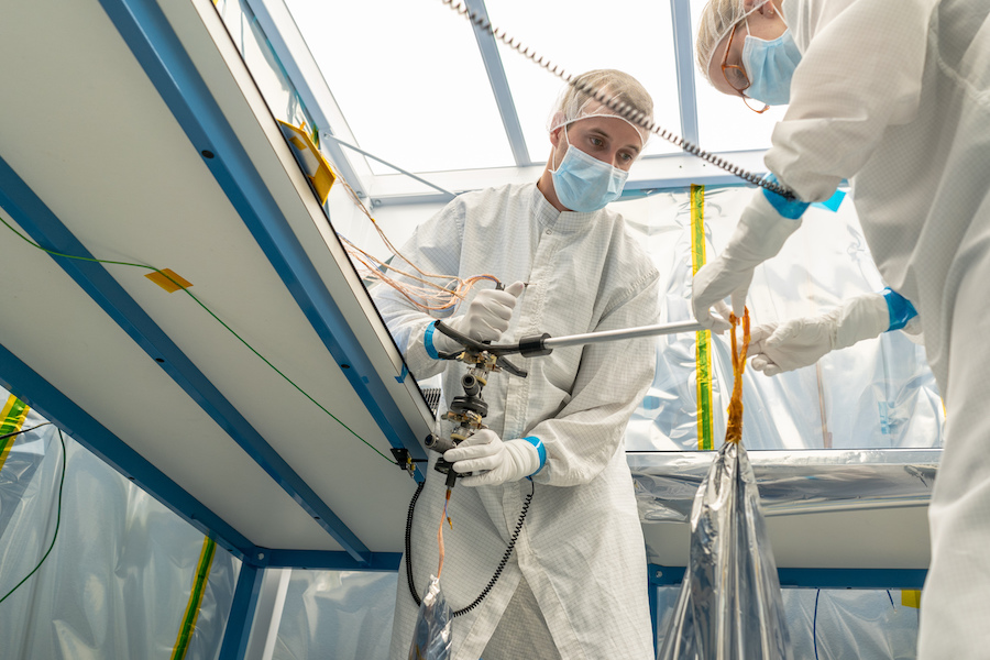
Keeping it clean, with Ben Pipenberg, Ingenuity engineering lead, and Sara Langberg, AeroVironment aeromechanical engineer. Photo courtesy of AeroVironment.
Systems Challenges
Ben Pipenberg [AeroVironment engineering lead on the program; senior aeromechanical engineer; joined AV in 2014; worked on sub-scale and larger demonstrators and the final build]
JPL handled pretty much all of the avionics development, all of the modeling and simulation, all of the sensors. They were attempting to leverage a lot of COTS hardware. The Bosch [IMU] sensor is a commercial off the shelf unit, the LiDAR system, the little cameras—both the return to earth and the GNC [guidance, navigation and control] camera. A lot of the navigation processing was done on a Snapdragon, which is a little commercial avionics board.
[But] there was a lot of custom design that went into making all of that work, and it’s all being interfaced into a lot of custom boards that JPL developed.
A lot of the features you can see on the helicopter were directly a result of GNC requirements. For example, flying in a Martian atmosphere, there’s very low damping; you’re essentially flying a gyroscope. And so, rather than having a huge rotor system, like what you would typically have on a helicopter here on Earth, we made a very, very stiff rotor system. And with a counter-rotating, coaxial helicopter like this, your net angular momentum is therefore zero.
Making the rotor system really rigid significantly simplifies how you can control that helicopter. And so, a lot of what you see on the helicopter in terms of even the rotor blade shape, very high taper, relatively thick for how low the Reynolds Number is on these rotor blades—that’s all for structural reasons. And that really defines a lot of the reason that the helicopter looks and is built the way that it is. So even though we didn’t work on the GNC side, we had to account for that in almost all of the design aspects just to make it controllable. And it was a very, very close collaboration between the GNC folks and the mechanical folks.
Chinese Weights and Tennis Racquets
Sara Langberg [aeromechanical engineer; joined the program in 2016; started with testing, especially on the blades; moved into mechanical design and fabrication, especially composites. Also swashplate geometry and building loads models for the blades and how that interacts with the servos, plus landing gear system in general]
One of the other things that occurs when we’re spinning at such a high RPM is different loads dominate than there would be on Earth. So the blades are subject to three loads. There’s the aerodynamic load and an inertial load of the blade through its rotations. But there’s also the propeller moment, which is called “the tennis racquet effect.” It’s the tendency of the blades at an angle to try to flatten themselves as they spin, and that’s due to having an off-axis center of gravity like we do.
On Earth, that’s a relatively small issue, and doesn’t often need to be accounted for. But because we’re spinning five to 10 times faster on Mars, this effect really dominates. In order to get the servo loads down and into a range where we can get good servo response, we added these counterweights, called Chinese weights, to the rotor. If you look at the blades, there’s a hollow carbon fiber cone on each of the blades and a tungsten ball in the tip that acts as a counterweight. That counteracts the propeller moment effect, and it doesn’t try to flatten itself quite so much. They’re optimized to reduce the servo loads the most at a hover condition.
Ben Pipenberg [We discovered the need] in the design process on the first full-sized helicopter. So that would have been like back in 2015. But there was something that AeroVironment had discovered with the high altitude airplanes on those propellers, because those were ground adjustable fixed pitch. They relied on essentially clamping the root of the propeller blades prior to takeoff. You set the pitch, you clamp the root of the blade take off, and then they would land after flying at high altitude, and they’d all have de-pitched themselves.
And so, one of the really senior scientists here brought up that this is probably going to be a problem. And yeah, it’s a problem.
Matt Keennon: And it’s not only the rotation of the entire blade, but the blades are actually twisted. And they’re actually trying to untwist and become flat. So it’s not only grabbing or counterweighting the whole blade, but it’s actually making the blade torsionally stiff enough. And that was another driver that fed into the mechanical design of the blades, which again, comes from our high altitude aircraft propeller designs.
We don’t want to add mass to the blade, but we can’t have them untwisting, we can’t have them unfeathering. So problems upon problems would crop up, and then we have to solve them in ingenious, lightweight, clever ways. Our background doing these other weird, lightweight, small aircraft, even like the Hummingbird, helped us think about these things in a different way and solve them.
Jeremy Tyler: So, on top of all that, the rotor blades are very highly cambered, is a very highly cambered airfoil, which is quite unusual for a rotorcraft, or at least for a cyclic pitch rotorcraft.
Matt Keennon: It’s inherently unstable. It can’t fly for a half-second without making decisions based on the IMU and driving the control system. We’ve tried flying this type of helicopter without a control system. It goes bad quickly. It’s just the configuration of a coaxial helicopter.
Jeremy Tyler: The coaxial router system has no gyroscopic damping whatsoever. So without a digital controller, without a gyro-based autopilot, it’s entirely uncontrollable. It’s much like a quadrotor would be without avionics system.
With all those aerodynamic loads of flying and camber and twist, still the inertial loads were dominant. And so Sara’s analysis, designing those counterweights to ideally balance the inertial loads to the aerodynamic loads, let us really optimize the servo weight and really minimize the size and power that was needed for those servos to get the bandwidth that was required from the GMC folks at JPL.
Part 3: The Meaning of Ingenuity will appear later this week.
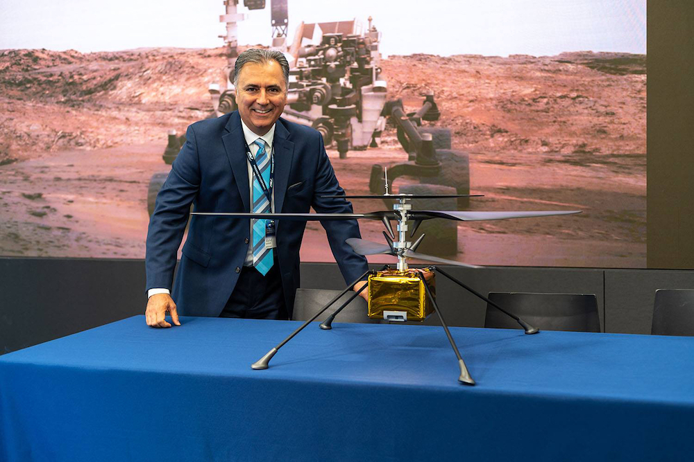
AeroVironment president & CEO Wahid Nawabi, up close with Ingenuity. Photo courtesy of AeroVironment.


